Let’s have a look inside the Altair 680 that I acquired at the hamfest a couple years ago.
Undoing four screws at the back of the unit releases the back (surprise!) and top cover to reveal the inside.

The back plate has the power supply consisting of two chunky transformers, a fan, and DB25 connector. There’s also an empty spot for another DB25 connector. Thanks to the two transformers, the rear panel is fairly hefty. The DB25 connector looks like it only has 4 wires. Not sure what would be connected to it, but probably something serial terminal related. There’s not a lot of clearance between the transformers and the SRAM chips on the main board when the rear panel is in place.


Removing the expansion board (I’ll get to that in a bit) reveals the main board.


The Motorola MC6800 CPU that powers the 680 is up toward the expansion board connector. Toward the bottom rear of the main board are 8 1kbit Intel P2102 SRAM chips that provides the 680 with 1 kB of RAM. Above the RAM is an EPROM (looks like an AM 1702A EPROM). The empty sockets seem like they would provide space for 3 more EPROMs. The other notable chip on the main board is the MC6850 asynchronous communications interface adapter.
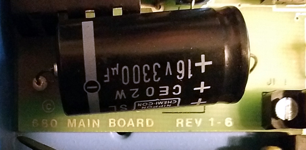
Over in the front corner of the board by the big 3.3 mF filtering capacitor, the silk screen says this 680 main board is Rev 1-6.
The only expansion board in this 680 appears to be a RAM expansion board. The riser card has room for 3 slots, but the two other spots are unpopulated.

The RAM board contains an 8×4 bank of Semi 4200UCP chips. A Google search didn’t yield a whole lot of information about them, but they appear to be 4kbit SRAM chips, so this board provides the Altair with a whopping 16 kB of additional memory to play with.

When I plugged it in and turned it on, the fan spun up and some lights came on!

No smoke released, but the data lights turning on even though most of the switches were in the down position indicates something’s not quite right. Changing the switch positions didn’t affect anything either. The Run light on even though the switch is in the HLT position also suggests something isn’t quite right. Toggling the HLT/RUN switch made the HLT LED blink on once. Toggling the RESET switch didn’t seem to affect anything. The address line switches all seem to work, but LEDs started blinking when A13 was switched on.


Looks like this unit might need some work to restore it to a functioning state. I’ll also need to do some more research to learn about how the 680 works.
Back into the closet it goes for now.
One Reply to “Peeking inside the Altair 680”
Comments are closed.