Radios: What do I want to get?

Amateur radio isn’t exactly an inexpensive hobby to get into. New base stations generally start in the $1-$2k range and go up from there. Portable/mobile radios a little less, usually in the $700-$1k range. There are a myriad of choices and sources available: new, used, vintage, auction sites, ham radio forums, hamfests, local users. For less $ and some elbow grease, you can still go the DIY route with a kit radio (a very intriguing idea). If you don’t know what you’re looking at or looking for, it can be pretty overwhelming.

Amateur radio equipment tends to be very modular, so it’s not just the radio you need. There’s also the power supply (another couple of hundred dollars), an antenna (or two, or three…how many bands do I want to play on?), and various and sundry accessories like filters, antenna tuners, maybe an amplifier and other things. It’s kind of like buying a car, and having to purchase the engine and tires separately. Most of the accessories can be acquired over time as the need for them arises, but the three basics are the radio, power and antenna.

I’ve been doing a lot of reading and a lot of browsing on ebay and swapmeet sections on various ham radio forums to get an idea of what’s out there and what’s available. I’m slowly starting to put together a list of what kind of gear I want.

I’m pretty sure I’m going to want at least two radios: a portable one for the car and a permanent station for the house. I’ll probably start with a mobile unit first. A third mobile/portable unit that I could take out and about with me without having to connect and disconnect what’s in the car would be nice too. That will probably be further down the road though. Both radios should be able to do HF/VHF/UHF, although I might consider VHF and UHF operation optional for the portable radio since I have my handheld.

As for specifics, I’m not partial to any particular manufacturer or brand. I think something new-ish so I don’t have to worry about it dying on me due to old age. There are some really neat looking old rigs up for auction on ebay that are tempting though. I don’t think I want to buy anything used online though. I’d much rather be able to play with it and see the radio in action beforehand, or know that the radio was actively used by the owner.

I’m not in a huge rush to get a radio just yet. This is the kind of thing I want to take my time researching and figuring out just what I want out of a radio set up. In the meantime, I’ll spend my time learning more about radio and getting more skill levels in electronics.
Amateur Extra in the books

My amateur radio license in the FCC ULS database changed from General to Amateur Extra this afternoon, so now it’s really official!

I put in the application for a vanity call sign, so in a few weeks I should be getting on the air with a shiny new and cool call sign.

Whee!

Still looking at radios and deciding what I want to get.

Measuring capacitance Part 2

I decided to explore a method for measuring the capacitance of an unknown capacitor using the capacitance measuring capability of my DMM. It has a range of 7 orders of magnitude (pF to 20 μF).

The total capacitance of capacitors in a parallel arrangement is just the sum of the capacitors.

C = C1 + C2 + ...

In series, the inverse of the total capacitance is the sum of the inverse of the capacitance of each capacitor.

1/C = 1/C1 + 1/C2 + ...

The total capacitance will be less than the smallest capacitor in the chain.

By placing the unknown capacitance in series or parallel with a known capacitance and measuring the resulting total capacitance, it becomes a pretty trivial matter to calculate the value of the unknown capacitor. Of course the total capacitance still has to be in the DMM’s measurable range.

In theory, either arrangement should yield the same result. I thought it would be interesting to see what kind of results I would get.

Armed with breadboard, some jumper wires and my DMM, I grabbed 5 capacitors that my DMM could measure. One capacitor served as my known (0.47 μF, which measured 0.442 μF according to the DMM). The other four would be my “unknowns”. Each of them was a 1 μF cap with measured values of 0.961, 0.0.964, 0.972 and 0.996 μF. By measuring the total capacitance with the capacitors in series or parallel arrangements, the unknown capacitance is easily calculated and can be compared with the measured value.

I ended up with some interesting results, but probably not terribly significant in the grand scheme of things.

Calculating the capacitance of the unknown capacitor in series with a known capacitor underestimated the measured value by 3%. Calculating the capacitance of the unknown capacitor in parallel with a known capacitor was more accurate, overestimating the value by just 1%.

I suspect most likely source of the difference between the two methods is due to stray capacitance in the breadboard or maybe in the DMM. It’s like having adding extra capacitor in network. With differences this small, I’d consider the two methods to be pretty much the same (as would be expected).

Some of the other “unknown” capacitors I have are pretty big, but armed with enough knowns and putting them in a suitable arrangement of series and parallel layouts, I should be able to bring the total capacitance down to something my DMM can measure, and be able to see just what the unknowns are.

Part 3 will probably see me exploring another method. I may need some more components for that though.

Measuring capacitance

Digital multi-meters have come a long way since I first used them. Back then all they gave you was voltage, current and resistance. My new DMM also has a temperature probe, measures capacitance and tests diodes and transistors.

During the process of sacrificing and dissecting a couple of old laptop power bricks, I’ve harvested a number of components, including transformers, inductors and capacitors.

Testing a capacitor to see if it’s still good is pretty simple by checking the resistance. Low resistance is bad, very high/infinite resistance is good, high but not very high is leaky.

I’d also like to know what the actual capacitance is, and how it compares to what’s printed on the capacitor. The capacitors I harvested are outside the measuring range of my DMM, so the easy way would be to just buy a capacitance meter to test them.

I don’t always do things the easy way though, especially when there’s an opportunity to learn something new. I’m pretty sure I can come up with a workable method to measure the “mystery” capacitors.

Adventures in electronics

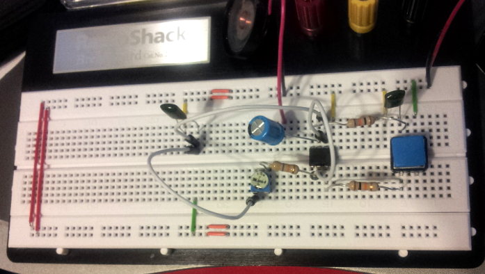
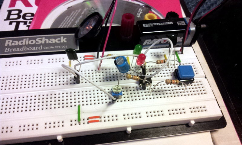
Finally found some time to sit down with all the bits and assemble a second Morse code key using the supplied schematic. At first it didn’t seem to work, but after checking through everything I found one of the speaker wires wasn’t fully inserted (short lead). After I fixed that, it buzzed at me when I clicked the button! The button is the clicky kind, so it’s not that well suited for doing Morse code, but it works! The buzzer was also a lot louder than the kit, which I later discovered was due to me forgetting a resistor between the final capacitor and speaker.

The next step was to make it light up in addition to buzzing. Spent some time looking at the schematic for a place to insert an LED that I didn’t think would make it go poof or fry anything. Put in a red LED and connected it to ground, pushed the button and it lit up! Then I decided to try a second green LED in series with the red, and they both lit up! Success!

A variable resistor instead of the fixed resistor in front of the speaker I think should give me some volume control, so I’ll try that next. I need to get one first.