Lately I’ve been getting a few calls from clinics looking for someone to perform ACRaccreditation surveys for their imaging equipment, mostly CT and nuclear medicine.
It’s a shame I don’t have more time to pick up more outside consulting. It’s a good way to pick up some extra income (although a good chunk of it ends up going to the government as taxes).
It’s probably better that way though. I have a hard enough time keeping up with all the x-ray equipment at work, never mind adding a bunch of other sites outside of work.
It’s not often I run into problems when testing x-ray equipment, but when I do they’re usually puzzling ones.
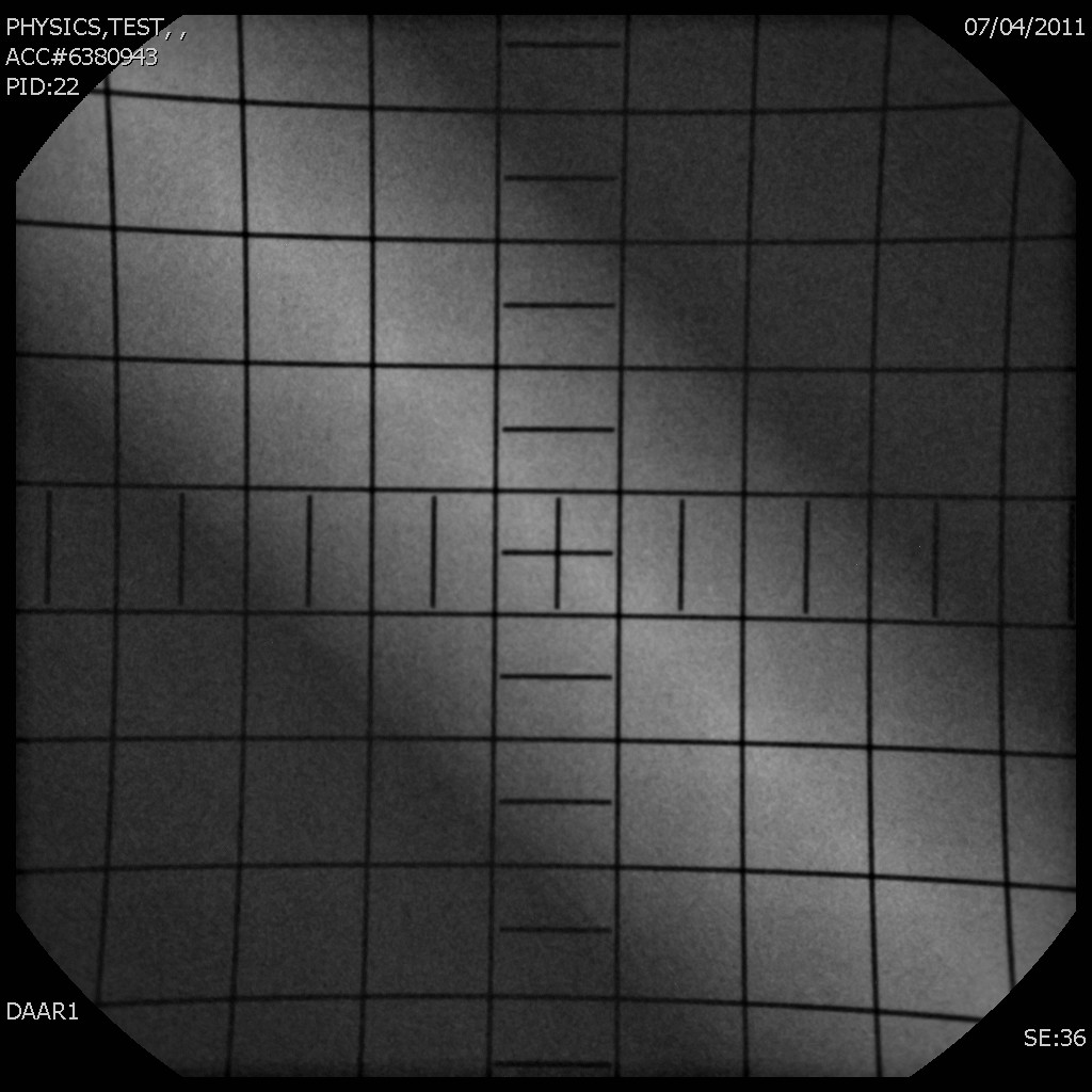
While I was testing a cath lab today, the lateral plane was giving me images that looked like
Ignore the grid pattern. That’s just one of my test objects.
At first I thought it was just a bolus filter getting in the way, but none of the usual buttons and joysticks for moving the filters made it go away. Wasn’t the bolus filters.
After giving it a little bit more thought, I realized it was the anti-scatter grid. It’s the exact type of artifact you expect to see for an upside down focused grid.
Popped the grid cover off to check, and sure enough the grid was put in backwards. Couldn’t figure out how to remove the grid to flip it around so I’ll have to leave it for the service guys to take care of. Coincidentally enough, the pages in the manual for inserting and removing the grid were missing.
In radiography, it’s not too unusual (although somewhat rare these days) to use a reversed focus grid as a kind of “poor man’s filter”, usually for chest imaging to even out the exposure differences between the lung fields and the mediastinum. I’ve never heard of this being this done for a fluoroscopy unit though. I don’t know if it was done deliberately or by accident.
One of the things I do with the radiology residents is do some practical labs with them, where they get to see some of the things they’ve been learning about in the classes we give them before they take the first part of their board certification exams.
A few months ago, it was a demonstration on the gamma cameras in nuclear medicine, where I attempted to show them how changing the image matrix size affects the image. Nuclear medicine images are typically acquired using matrix sizes ranging from 642 all the way up to 10242. Most are acquired using a 1282 image matrix size.
Generally, as you increase the matrix size, the resolution of the image improves. Most people might think that because of this, you should always use the highest matrix size possible, because that will give you the best image. But you’d be wrong.
Nuclear medicine images are acquired either for a fixed time, or a fixed number of counts. Let’s suppose an image is acquired containing a total of 106 (1 million) counts. If the image matrix size is 642, that 106 counts is spread out over 4096 pixels (which gets you about 244 counts/pixel).
Below is an image of a bar quadrant phantom acquired in a 642 matrix for 106 counts.
It’s a fairly smooth looking image, not a lot of noise, but none of the bars are resolved.
If that image matrix size is 1282 instead, now that million counts is spread out over 4 times as many pixels (16384 pixels), and now you only have 61 counts/pixel. Below is the same bar quadrant phantom, same 106 counts but acquired in a 1282 matrix size
Now one set of bars is visible but the noise has increased a little bit.
You can resolve smaller structures with the larger matrix size, but now the count density of your image has decreased by a factor of 4 (and the noise in your image has also increased).
Let’s go to 2562
The next set of bars is visible but notice how the noise has increased significantly.
Let’s see what 10242 looks like. You might expect that we would be able to see even more bars at this matrix size.
Nope, no more bars visible, and the noise has really gone up. At 10242, the count density has decreased to less than 1 count/pixel.
Of course there are ways around this. At higher matrix sizes, you can acquire more counts in your image but this requires either imaging with more activity in the patient or imaging for a longer time, which may or may not be feasible.
Photographers, take note. The same thing happens with digital cameras. Naturally, the amount of light digital cameras capture is orders of magnitude higher than in nuclear medicine, but problem is the same. More megapixels (MP) is not always better.
One of the new Siemens Symbia gamma cameras developed problems serious enough to require the entire head to be replaced. Naturally I took the opportunity to get in and take some pictures of the innards.
This is the head assembly with the photomultiplier tubes (PMTs) wrapped in sleeves of mu-metal. The mu-metal shields the PMTs from stray magnetic fields.
Looking down at a couple of the PMTs. To fill in the empty space at the edges, smaller PMTs are usually used.
Learned today that I’m being kicked out of the office I’ve been in for the past 9 years and moving to another slightly smaller office next door. Have to get all my crap moved over by the end of the month. A guy can collect a lot of crap over 9 years, so part of the move will involve a lot of downsizing. There’s a bunch of junk I can probably get rid of so downsizing should be pretty easy. Still, moving is a pain in the butt, even if all I’m doing is going next door.
I envision spending the next few months accidentally walking into my old office area before I get into the habit of remembering where my office actually is.