PET Shielding

Ever wonder what goes into shielding for a PET imaging facility?

No? Well, I’m going to show you anyway.

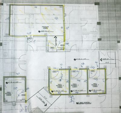
First you need to find a Qualified Medical Physicist (like me) to develop a shielding design for you. The shielding design gets turned into a set of blueprints for the lead contractor to work with.

Shielding blueprint

Then you need lead. Lots and lots of it.

Lead bricks
Lead lined plywood sheets


This is a layer of 1/4″ thick lead sheet lining the floor. The strips cover up the seams between the lead sheets so that there are no gaps. Depending on what’s underneath, the floor may require as much as 1″ of lead.

Floor shielding
Lead sheet used for floor shielding

For the walls, you’ll need stacks of 1/4″ or 1/2″ lead sheet attached to 3/4″ plywood, like these

Lead wall sheets

Thinner lead sheets are usually glued to drywall, but that doesn’t quite cut it for the thicknesses required for PET shielding.

The lead/plywood sheets go up like this

Lead/plywood wall

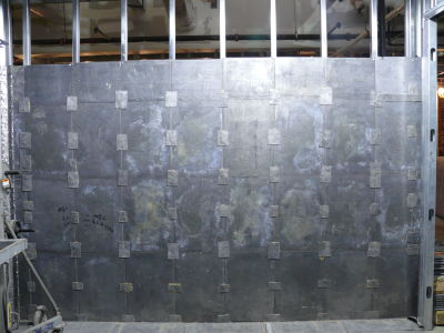
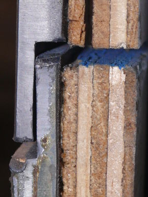
The sheets are also interlocking to eliminate the gap between sheets

Interlocking lead joints in the plywood wll

Depending on what’s on the other side of the wall, you’ll need bricks too. This is a stack of 1″ interlocking bricks. Sometimes your wall might even need up to 2″ thick bricks.

Stack of lead bricks

This is what the brick wall ends up looking like

Lead brick wall

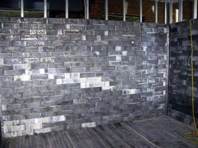
The bricks are screwed into the metal studs for support. Thicker brick walls require additional support and are usually constructed between two sets of studs.

Journal Club: Simultaneous Acquisition of Multislice PET and MR Images: Initial Results with a MR-Compatible PET Scanner

Today’s journal club article comes from JNM and talks about some new bleeding-edge tech alluded to in the previous journal club article: PET and MRI.

The technology presented in the paper is pretty bleeding edge and represents 2 years of instrumentation and development work. They present a prototype PET unit for use in a small animal MR magnet operating at 7T. Their solution to solving the problem of detecting light from the scintillator crystals was to use position sensitive photodiodes, which are less prone to distortions from magnetic field effects. In order to reduce electrical noise in the detectors, the authors used a cold nitrogen gas to cool the detectors. This is understandably a significant limitation for real world clinical work, but not insurmountable. Several interesting effects were noted with using the photodiodes and fiberoptic coupling and are nicely illustrated with sample images.

Some very interesting development work here that shows a lot of potential. It’s not the first PET/MRI hybrid unit developed or the only one being worked on, but the design and implementation the authors have come up with has the potential of retrofitting existing MR scanners with the capability rather than having to get a new magnet. Obviously it’s still several years away from any kind of implementation for human use, but in the meantime a working unit for small animal imaging would probably yield some very useful information for researchers.

Ciprian Catana, Yibao Wu, Martin S. Judenhofer, Jinyi Qi, Bernd J. Pichler and Simon R. Cherry, “Simultaneous Acquisition of Multislice PET and MR Images: Initial Results with a MR-Compatible PET Scanner“, J Nucl Med 47: 1968-1976

Abstract:

PET and MRI are powerful imaging techniques that are largely complementary in the information they provide. We have designed and built a MR-compatible PET scanner based on avalanche photodiode technology that allows simultaneous acquisition of PET and MR images in small animals.
Methods: The PET scanner insert uses magnetic field-insensitive, position-sensitive avalanche photodiode (PSAPD) detectors coupled, via short lengths of optical fibers, to arrays of lutetium oxyorthosilicate (LSO) scintillator crystals. The optical fibers are used to minimize electromagnetic interference between the radiofrequency and gradient coils and the PET detector system. The PET detector module components and the complete PET insert assembly are described. PET data were acquired with and without MR sequences running, and detector flood histograms were compared with the ones generated from the data acquired outside the magnet. A uniform MR phantom was also imaged to assess the effect of the PET detector on the MR data acquisition. Simultaneous PET and MRI studies of a mouse were performed ex vivo.
Results: PSAPDs can be successfully used to read out large numbers of scintillator crystals coupled through optical fibers with acceptable performance in terms of energy and timing resolution and crystal identification. The PSAPD-LSO detector performs well in the 7-T magnet, and no visible artifacts are detected in the MR images using standard pulse sequences.
Conclusion: The first images from the complete system have been successfully acquired and reconstructed, demonstrating that simultaneous PET and MRI studies are feasible and opening up interesting possibilities for dual-modality molecular imaging studies.