DLink DIR-655 autopsy

On the dissection table today is the old D-Link DIR-655 wifi router that kept flaking out last year.

Getting the cover off wasn’t too difficult. Two screws hidden under the rubber feet are all that need to be removed. A little bit of gentle pushing and prying undid the clips that hold the top cover on revealing the guts of the beast.

Inside a DLink DIR-655 wifi router

The inside is relatively sparse. The large black boxes at the top are the RJ-45 connectors. Based on the icon printed on the HN4843CG and HN2443CG objects below them, I’d guess they’re isolation transformers for the RJ-45s. The bits under the metal shield are probably the wifi radio-related parts.

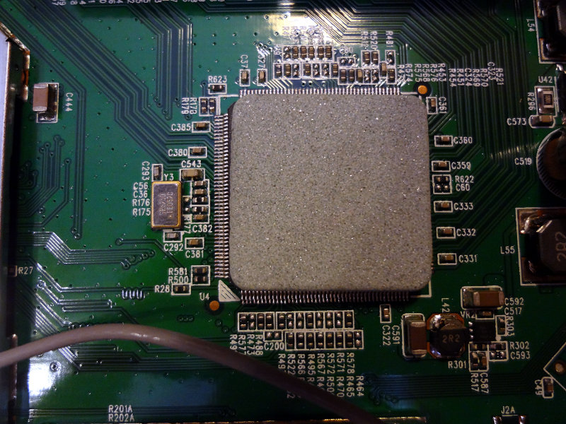
The large gray thing is some kind of stone-like substance acting as a heat sink for the large chip underneath. It’s held on by a piece of thermal tape. A little bit of prying popped it off pretty easily revealing an Atheros IC (AR 8316) which I think handles the ethernet stuff.

Gray stone-like object attached to a large integrated circuit on the main board of the DIR-655 router
Atheros AR 8316 IC

To the left of the shielded bit, the most interesting thing is an IC labeled MX25L6445EMI-10G which is a 64Mbit flash memory chip.

MX25L6445EMI-10G 64 Mbit flash memory chip

Underneath the RF shield are a few other large ICs: an Atheros AR9223 802.11b/g/n wifi module, an Ubicom IP7150U which appears to be the actual router controller and a Zentel A3R12E4JFF IC (SDRAM perhaps?).

ICs underneath the RF shield

I didn’t see anything obvious to explain why the router kept flaking out. The thermal tape holding the heatsink rock to the AR 8316 chip was mostly holding on by the edges and corners and the sticky part in the center area was shiny, suggesting it wasn’t making very good contact with the chip anymore. Overheating could certainly explain intermittent issues. Would be an easy fix with some new adhesive thermal compound and a low profile heatsink. The RF shield got mangled a bit in the removal process though, so this board is off to the workbench.

Resistor storage

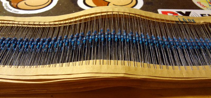
At the hamfest back in February, I picked up a big bag of resistors that’s been sitting on the shelf since then. They turned out to be 50 strips with 50 resistors each. The values are conveniently printed on the paper strip, which saves me time decoding the stripes on the resistors.

Strips of blue 1% precision resistors

I don’t have room in any of my storage bins to hold them all, and searching through them in that pile isn’t the most convenient thing. Then I remembered reading a while ago about someone using pill bottles to store components in. It seemed like a workable idea, and I happened to have a bunch of them sitting around. I don’t have enough for all of the strips, but I can get more pretty easily.

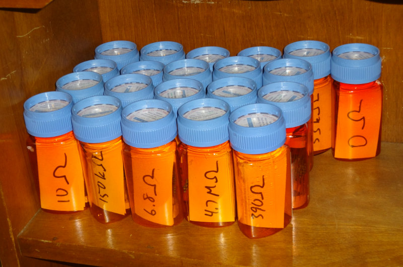
I wrote down the resistor value on a sticky note folded in half, rolled up a strip of resistors and stuck it into the pill bottle. I had enough bottles on hand to do 21 of strips, leaving 29 left to go.

Resistors organized into pill bottles for storage

I figure I can order them into three groups, 100 (Ω), 103 (kΩ) and 106 (MΩ). The big printing should make it pretty easy to find the ones I need.

MeSQUARES and MePADS

After seeing Dave/AA7EE‘s many amazing builds using the MeSQUAREs from QRPme.com, I finally got around to ordering a few for myself to play with. Ordered 2 sets (600 pads) of MeSQUAREs and a set of MePADs. The order arrived today along with a couple of bonus sheets of copper clad PCB. Very thoughtful of W1REX to include them.

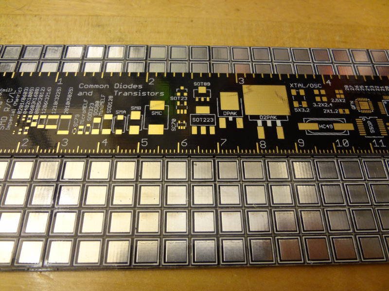
Although I’d seen them in all of the pictures Dave posted, their size still surprised me a bit.

A panel of QRPme MeSQUARE pads with a ruler laid on top for scale.  Each pad is about 6x6 mm square.

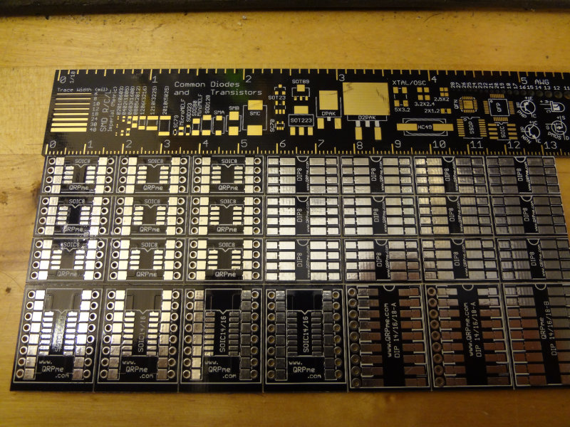
Each square is about 6 mm (0.2″) on each side, so not too terribly small to work with. The MePADs come in a slightly smaller sheet and are used for making the pins of smaller ICs a little more accessible.

A panel of MePADS for adapting surface mount SOIC integrated circuits to through hole

Looking forward to experimenting and building things with these. I don’t know if I’ll be able to match Dave’s aesthetic, but it gives me something to strive for.

Si5351 breakout board

Jason/NT7S launched the crowdfunding campaign for his version of an Si5351 breakout board last night, and already this morning it’s at over 150%. The stretch goal at $1 500 involves spending some more time on the software library to make the board easier to use.

It’s a neat little oscillator chip that seems to provide a lot of capabilities for not a lot of money. He’s been documenting his investigations on the chip at his blog for the past year now, including building a couple of receivers and transceivers around the Si5351.

The Si5351A is quite a capable IC at a very modest price. It is a PLL clock generator with three independent outputs which can each generate a separate signal from 8 kHz to 160 MHz. A 25 or 27 MHz reference oscillator is used for the two internal PLLs (the Etherkit breakout board uses a 25 MHz reference oscillator), which allows the user to choose the amount of frequency stability and accuracy required.

Go check out the Si5351 breakout board campaign on Indiegogo, and pick one up if it’s something you’ll find useful in an upcoming project.

Arduino thermometer

Started with my first big Arduino project using one of the Sparkfun Redboards and my new *duino work station.

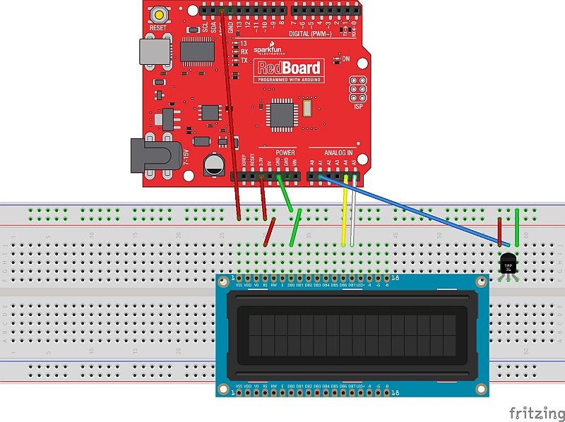
The Adafruit RGB LCD shield and TMP36 temperature sensor were pretty easy to wire up to the Redboard. The LCD shield communicates using the I2C pins, so it just need those to connections plus 5V power and ground from the Redboard. The TMP36 was just as easy to wire using 3.3V power and ground from the Redboard and connection to one of the Redboard analog inputs.

Fritzing schematic illustrating connections from a Sparkfun RedBoard, an LCD display module, and a TMP36 temperature sensor

(There was no Fritzing part for the LCD shield, so I just used an LCD display part instead)

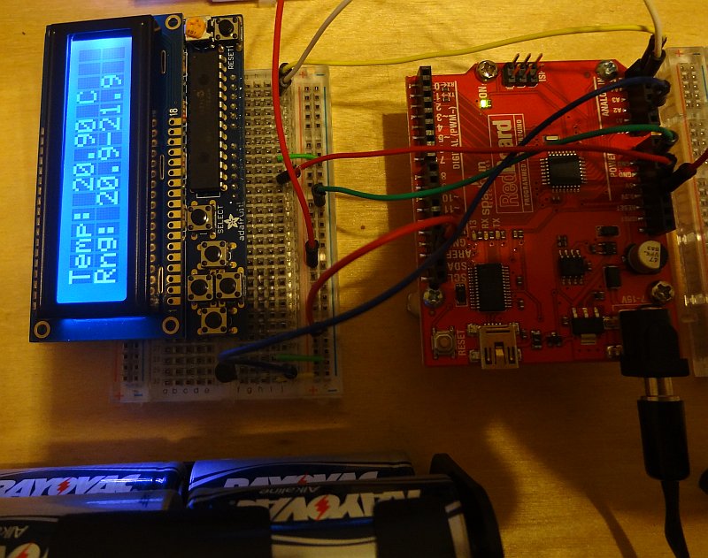
A few hours of writing some code and fiddling around got me a working thermometer.

Sparkfun Redboard connected to a breadboard containing an LCD display module

Thanks to the Adafruit RGB LCD library, the sketch for what I’ve done so far is pretty simple. Pressing the Select button on the shield makes the LCD turn on and display the current temperature as well as the range of temperatures measured since it was turned on. The temperature is displayed for 30 seconds, then the LCD and backlight are turned off. Pressing the Select button again makes it display the temperature again.

The next step will be to add some additional functions accessed via a menu. I’ll add a speaker or buzzer and have it alarm above a certain temperature. Once I have this prototype working nicely, I’ll repackage it and turn it into a thermometer to monitor the temperature in our freezer. I’ll have to figure out how to attach the thermometer to the power and analog pins, because the LCD shield doesn’t break them out. Shouldn’t be too hard to work out.