IC Inventory

After using up some spare time over the period of a few weeks, I finally finished going through the parts bin of ICs and inventoried them. Right now it’s a big long list in a Google Drive spreadsheet.

I don’t know what most of them do, have no idea if any of them are still functional and probably won’t ever use any of them, but I did have fun going through them, digging up datasheets for them and reading the descriptions for each of the chips. Datasheets for most of them were pretty easy to find, while a few others I had to dig a bit. There were a handful that I wasn’t able to find anything on.

About a half dozen of the bins had EEPROMs in them, which I ignored for the most part. One bin had a stash of 555 timer chips that could find some use in a project if they work. There are CPUs, digital logic gates, op amps, buffers, registers, counters, even some RAM chips. If I had the know-how, I’ve probably got just about everything I need to assemble a simple computer based on the Z80 CPUs I found in the bins.

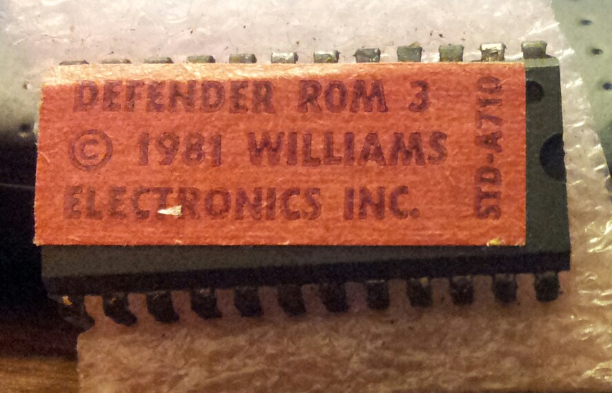
One interesting find in one of the bins was this Defender ROM.

DefenderROM.jpg

Absolutely no idea if it’s any good, but it would be neat to plug into a Defender console and see if it does work.
Exploring Arduino

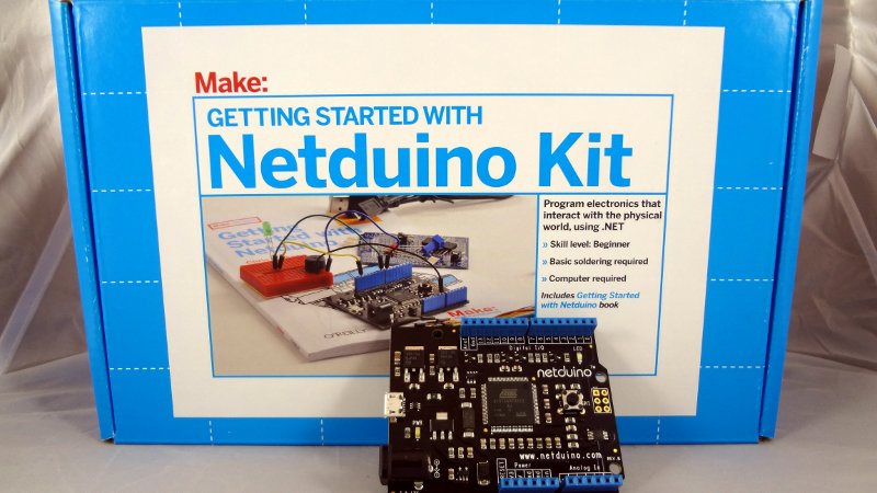
I found the Make Getting Started with Netduino kits on clearance at Radio Shack for $20, so I decided to pick one up (rescuing more clearance items). Figured it would be a good way for me to get my feet wet in the Arduino and microcontroller world.

A Make: Getting started with Netduino kit and a Netduino board

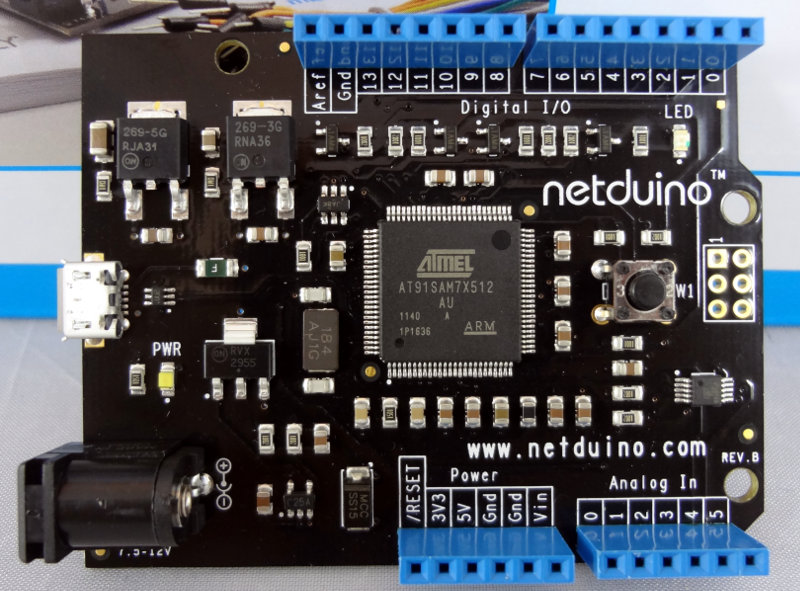
The board it self is pretty small, maybe a little smaller than 10x10cm.

A Netduino microcontroller board.  The board has the same form factor as an Arduino microcontroller board.

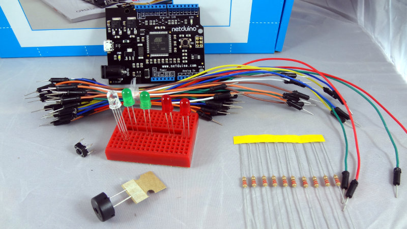
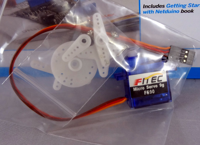
The kit contains everything you need for the basics like making LEDs blink, a little speaker, a little bread board for prototyping and even a servo motor.

A Netduino microcontroller board, bundle of connector wires, a red mini breadboard with some LEDs in it, a small push button, speaker, and a strip of resistors
Ziplock bags that contain a small servo motor

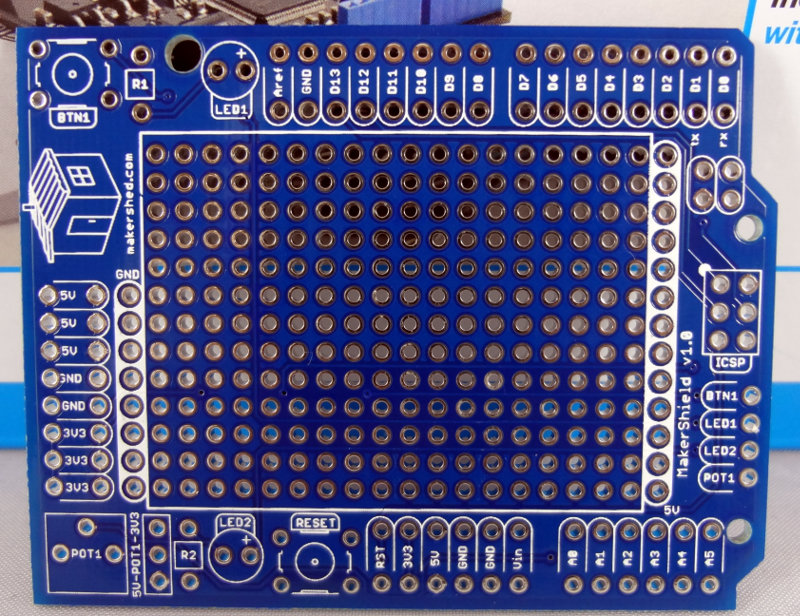
There’s even a MakerShield included for building your own Arduino shield.

Makershield prototyping board

I’ll have to deal with C# and .NET, but I don’t think it should be too difficult. I’m looking forward to learning and playing with it.

Project: Camera intervalometer

I’ve decided to embark on my first circuit design project. Going to try to build myself an intervalometer that I can use with my camera.

My plan is to take what I’ve learned (and will learn) about 555 timers and try to build a circuit that will generate pulses at variable intervals. The pulses will (somehow) short a connection to ground, triggering the camera shutter with each pulse.

Sure, I could do this the easy way and go with one of the many designs posted at places such as Instructables, but coming up with it myself will be much more educational.

Decision maker

Lately I’ve taken to browsing my local Radio Shack and “rescuing” some of the clearance items I come across.

Today I wandered in looking for some terminal lug strips and came out with 60′ of hookup wire (can never have too much wire around, right?) and a neat little Velleman Decision Maker kit, both of which were on clearance.

About 15 minutes at the bench, and this simple little kit was all assembled. It’s basically a binary magic 8 ball. Press the button and the LEDs flash quickly, eventually slowing down until one of them stays lit.

Assembled board for a Velleman Decision Maker kit

It’s all through hole components, and is very easy to assemble making it an excellent kit for someone learning how to solder. Perfect for introducing soldering techniques to a kid.

Not bad for $2.

Binary clock innards

I noticed that one of the lights on my binary clock wasn’t lighting up anymore, and another one was only lighting up very dimly. Thinking that maybe it would be a simple fix to replace some LEDs, I popped it open and have a look inside. It was pretty easy to open up with just 4 tabs to unclip.

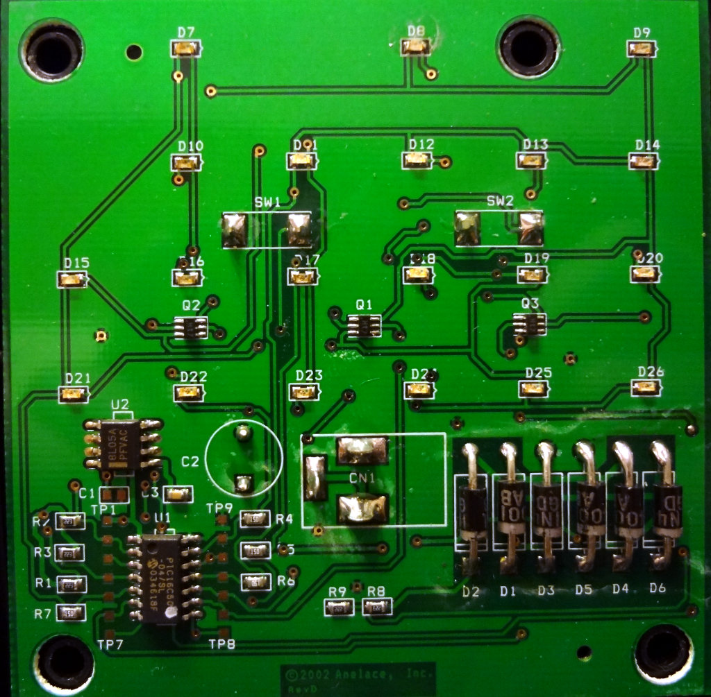
Everything is all on one board with surface mount LEDs (labeled D7 – D26) instead of the regular LEDs I was expecting.

Binary clock circuit board

The dead diode is D24, and the fading one is D18.

The six 1N4001 diodes do some rectification of the 9VAC input power. I haven’t traced out the circuit yet to see how they’re arranged.

A PIC16C505 microcontroller is the heart of the binary clock. The other chip above the PIC controller (U2) is a 5V voltage regulator, which provides the power to the PIC controller.

I wonder how hard it would be to find some LEDs to replace the dead ones with.

Update: Traced out the arrangement of the diodes and this is what it seems to look like.

Schematic for the power rectification part of the binary clock


It’s a bridge rectifier taking the 9V AC input and doing full wave rectification