Binary clock innards

I noticed that one of the lights on my binary clock wasn’t lighting up anymore, and another one was only lighting up very dimly. Thinking that maybe it would be a simple fix to replace some LEDs, I popped it open and have a look inside. It was pretty easy to open up with just 4 tabs to unclip.

Everything is all on one board with surface mount LEDs (labeled D7 – D26) instead of the regular LEDs I was expecting.
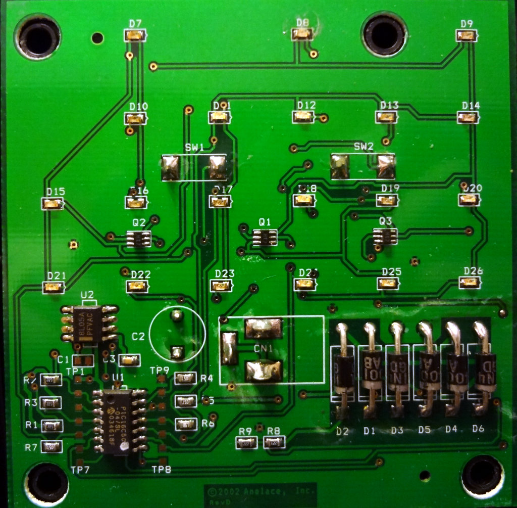
Binary clock circuit board

The dead diode is D24, and the fading one is D18.

The six 1N4001 diodes do some rectification of the 9VAC input power. I haven’t traced out the circuit yet to see how they’re arranged.

A PIC16C505 microcontroller is the heart of the binary clock. The other chip above the PIC controller (U2) is a 5V voltage regulator, which provides the power to the PIC controller.

I wonder how hard it would be to find some LEDs to replace the dead ones with.

Update: Traced out the arrangement of the diodes and this is what it seems to look like.

Schematic for the power rectification part of the binary clock


It’s a bridge rectifier taking the 9V AC input and doing full wave rectification

Advent candles

With just one mold to use, the Advent candles took a few days to make, but I finished the last of them today. I made two sets of Advent candles: 6 purple, 2 pink and 2 white candles all together. I ended up with just enough wax of each colour left over to make a set of votives too.

The purple ended up a little darker than I planned. Forgot how concentrated those wax colour blocks are. The pink ones look more reddish in the photo, but they’re definitely pink-ish. Still need to do a bit of finish work on the candles. The bottoms need to be flattened so they stand up straight, wicks need to be trimmed and the sides polished up a bit.

Coils!

In addition to the air variable capacitors, three of the parts bins contained a bunch of pre-wound antenna coils, including these that looked unused. One of them even had an instruction sheet.

Calrad CLS Loopstick.

Calrad CLS loopstick antenna

They consist of two coils, one wound on top of the other and what seems to be a ferrite rod inside that can be tuned by turning the screwdriver or even a knob at the other end.

Coils on the loopstick antenna
Tuning slugs on the loopstick antenna coil

One was also in a box, a Miller A-5495-A with two separate coils and a capacitor. Looks like it has a tuning range of 540 – 1700 kHz, which is the AM broadcast band.

Miller A-5495-A antenna coil

This one was tunable as well by turning the screw at the end.

Tuning slug in the Miller antenna coil

Now, if I can find some Ge diodes, I wonder if I could use these in a crystal radio

Adding to the air variable capacitor collection

While exploring the component bins, I came across a couple of air variable capacitors, one of which was still in the box and didn’t look like it had ever been used. A Hammarlund APC-50-B air padding capacitor, complete with knob. Capacitance range is 3.9-50 pF. Looks in really good condition and turns pretty smoothly.

Hammarlund APC-50-B variable capacitor
Hammarlund variable capacitor

The other air variable capacitor I found is a little more anonymous but also looked like it hadn’t been used before. One of the rotor plates at the very back was slightly bent causing it to make contact with a stator plate. Aside from that it seems in good condition and turns pretty well.

Variable capacitor

I’ll have to see if I can straighten out that one plate. Would be cool to use it in something.

Monitor repair Part 2

Took me a little bit longer to get to than I planned, but I finally got the capacitors replaced. The diameter of the 820 ÎĽF capacitors were a little larger than the original ones, so it was a bit of a tight fit getting the three of them in. While I was in there, I replaced two other 820 ÎĽF capacitors in the middle of the board even though they still looked in good shape. Thought about replacing the 22 ÎĽF and 47 ÎĽF capacitors, but decided not to. There were a lot of surface mount components near the 22 ÎĽF cap and I didn’t want to get the soldering iron too close or accidentally solder where I shouldn’t.

Took me a bit of time to remember how everything went back together, but I got the monitor reassembled and brought it back to the computer. Plugged it in, turned it on and was rewarded with the monitor telling me it was trying to find a signal source. Reconfigured the computer for a second display and up it came!

Monitor is fixed and now I’m back to a dual headed system.

Woot!