Arduino thermometer

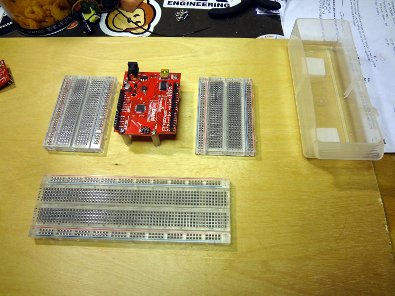
Started with my first big Arduino project using one of the Sparkfun Redboards and my new *duino work station.

The Adafruit RGB LCD shield and TMP36 temperature sensor were pretty easy to wire up to the Redboard. The LCD shield communicates using the I2C pins, so it just need those to connections plus 5V power and ground from the Redboard. The TMP36 was just as easy to wire using 3.3V power and ground from the Redboard and connection to one of the Redboard analog inputs.

Fritzing schematic illustrating connections from a Sparkfun RedBoard, an LCD display module, and a TMP36 temperature sensor

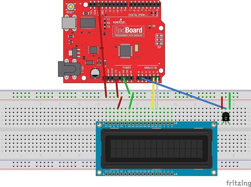
(There was no Fritzing part for the LCD shield, so I just used an LCD display part instead)

A few hours of writing some code and fiddling around got me a working thermometer.

Sparkfun Redboard connected to a breadboard containing an LCD display module

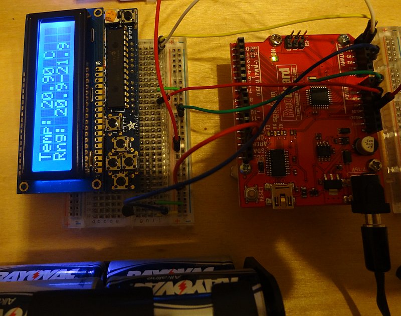
Thanks to the Adafruit RGB LCD library, the sketch for what I’ve done so far is pretty simple. Pressing the Select button on the shield makes the LCD turn on and display the current temperature as well as the range of temperatures measured since it was turned on. The temperature is displayed for 30 seconds, then the LCD and backlight are turned off. Pressing the Select button again makes it display the temperature again.

The next step will be to add some additional functions accessed via a menu. I’ll add a speaker or buzzer and have it alarm above a certain temperature. Once I have this prototype working nicely, I’ll repackage it and turn it into a thermometer to monitor the temperature in our freezer. I’ll have to figure out how to attach the thermometer to the power and analog pins, because the LCD shield doesn’t break them out. Shouldn’t be too hard to work out.

Inside a cassette adapter

Found one of these rummaging around in the car the other day.

Audio cassette adapter

If you have no idea what this is or don’t get what it’s for, ask your parents.

The cassette player in the car kept spitting it out, so I figured I’d open it up to see what was inside.

Cassette adapter disassembled

Surprisingly simple inside and much less than I expected. Just the magnetic read/write head and a single circuit board.

Cassette adapter circuit board
Cassette adapter read/write head

There are just a couple of capacitors and a couple of resistors (on the other side of the board), so it’s a very simple circuit.

Cassette adapter schematic

The resistors are pretty big, 820 MΩ, presumably to knock down the input down to something the cassette player can deal with.

*duino work station

Inspired by the Sparkfun Arduino and Breadboard holder, I decided to build my own portable work station to use for building projects with my *duinos.

I cut a 27.7cm x 40.5 cm piece of 6mm thick (1/4″) plywood from stuff I had on hand to serve as the base, and started playing around with how I wanted things laid out. I eventually settled on a setup with three breadboards around the *duino board (in this case, a Sparkfun RedBoard) and a little parts bin on the side.

Sparkfun RedBoad workstation with breadboards

Scrounged up some nylon standoffs and screws to mount the board to the plywood and I ended up with this.

Sparkfun RedBoad workstation with breadboards

I can switch between the Netduinos and RedBoards pretty easily, and it gives me plenty of breadboard space to work on. The parts bin stays on the board thanks to the magic of Velcro and I used the adhesive backing on the breadboards to stick them to the plywood.

Still have plenty of room on the left side to put other things. Now I’ll be able to easily pick up my projects and move them somewhere else to work on.

Ugly construction attempt

My first attempt at building a circuit using the ugly construction technique. It’s supposed to be a simple oscillator circuit using a J310 transistor.

Ugly construction oscillator circuit

One of the advantages of ugly construction is that if you’re working from a schematic or circuit drawing, building is pretty easy. I found that soldering components to the copper clad required a bit of patience, because it’s essentially a very large heat sink. Put the soldering iron on the copper clad, add solder until you get a good sized pool, leave the soldering iron in place and place the component.

For this particular circuit, Vcc is applied to the big resistor with the free lead and output is off the capacitor with the free lead. I soldered on a piece of wire to make the ground connection easier. Haven’t applied power to test it out yet. Will see if it works later on.

Nexus 5 X-ray – Hi Res

A little while ago, I took a radiograph of my Nexus 5 using a conventional radiographic unit.

Today, I was doing some testing on a mammography unit and acquired another x-ray of my Nexus 5. The mammography unit uses a much smaller focal spot, and will produce much sharper images. However, with the much lower kV mammography units use, it’s a lot harder to get adequate penetration through denser objects (like circuit boards and batteries).

This image was acquired at 34 kV and 120 mAs using the large (0.3 mm) focal spot. Its pretty easy to see that this one is a lot sharper than the other image (click the image to embiggen to all it’s glory).

Nexus 5 X-ray
Nexus 5 X-ray

The main circuit board area towards the top as well as the battery is harder to see through than the other version, because of the lack of penetration of the low energy x-rays. It’s a lot easier to see some of the detail in the circuit board at the bottom of the phone, because there’s less to go through there.